Improvement and Application of Debugging Method of CNC Machine Tool in FANUC System
Abstract: The design and commissioning process of PMC program was introduced with the tool-cutting machining center as a platform. The three aspects of the emergency stop signal of the switch shaft, the debugging of the status indicator of the unloading knife, and the position detection and debugging of the rotary shaft were applied to the FANUS system. The operation method and the debugging process are discussed. It is pointed out that the PMC has stable machine operation and convenient debugging for the CNC machine tool debugging and improves the work efficiency.
Keywords FANUC; PMC; CNC machine tool; debugging method In the numerical control machine tool industry, the numerical control system refers to the computer numerical control device, programmable logic controller, feed drive and spindle drive device and other related equipment. Sometimes it refers to the computer digital control device and the control device is called a numerical control device. The composition of the numerical control system and the role of various parts, as shown in Figure 1.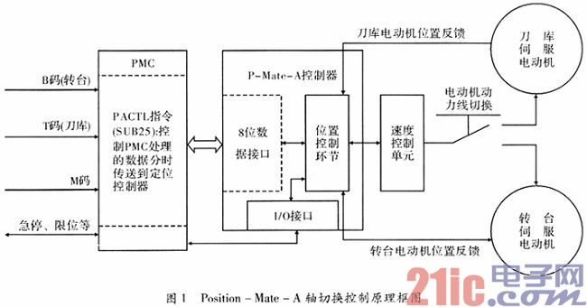
From the block diagram of the Position-Mate-A axis switching control in Figure 1, it can be seen that the single-axis CMC operating system is mainly applicable to tool magazines. This requires a continuous and more accurate positioning of the CMC system. The machining center consists of the following structures: Positioning controller, two servo motors, one servo unit. These devices are mainly used for the control of the magazine turntable. The machine tool has an advantage that the turntable and the magazine do not need to act at the same time, which avoids equipment wear due to friction and other reasons, so as to achieve the purpose of reducing costs.
The specific steps for the issuance and processing of program instructions are: (1) The CNC controller is responsible for issuing instructions to the PMC. (2) The PMC processes and issues control and movement instructions based on the calculations issued to the CNC. The role of the turntable operation instruction and the axis switching instruction is to change the operation mode of the controller. That is, the operation of the magazine is changed to the operation of the turntable. The specific flow is: (1) the servo is in the disconnected state; (2) the servo motor power line is switched; (3) the position controller is changed from the magazine mode to the turntable mode; (4) the servo is turned on; (5) the specified position is reached .
It is noteworthy that after the above steps are completed, the operation mode of the tool magazine is switched to, and the emergency stop signal needs to be switched to the controller emergency stop interface.
Many accidents usually occur during the operation of the machine tool. The operator must analyze it based on experience. When the tool magazine is violently shaken, the damage degree of the various components in the tool store will be deepened. This phenomenon occurs because the controller is in a reset state when the emergency stop is released. At this time, the operation mode of the axis is changed. However, actually, the instruction is not executed, so an abnormal axis switching action may occur. After analyzing and researching the above problems, it has been found that using common methods to solve this problem has not achieved good results. Through practical research, it has been found that using the following methods to solve this problem will have satisfactory results. That is, the output is in the off state during the conversion process, which will not cause severe vibration of the tool magazine. According to the above analysis, the PMC emergency stop circuit is improved, as shown in FIG. 2 .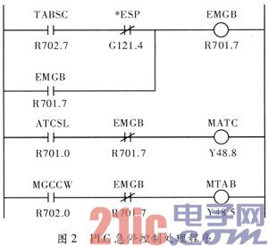
The specific analysis is as follows: During the rotation of the turntable, press the emergency stop button. The ESP signal is switched on with the EMGB and then unlocked by itself. The signal will not change if the total power is not removed. Therefore, although the CNC has returned to the initial state, the EMGB signal is always "1", and the output signal for switching the turntable and magazine is always "0", which causes the two switching contactors to be powered off at the same time and positioning The controller and servo unit are in an alarm state. At this time, the CNC will send an alarm signal and information prompt. If you want to cancel the alarm, you must cut off the power and restart the machine. The above method can fundamentally eliminate the fault.
1. ATC loading and unloading knife status indicator debugging analysis A machining center uses a separate structure tool magazine robot and uses a hydraulic cylinder method to complete the tool changer. The robot rotates 180° clockwise on the spindle side to complete the tool change. The sensing block triggers LS+180° and thus proximity switches to get bit detection. In the next tool change process, the robotic arm reverses 180° to realize tool change, and the sensing block triggers LS+180° to approach the switch to obtain bit detection. From the analysis of the above-mentioned tool change procedure, it can be concluded that the manipulator needs a forward/reverse 75° motion to achieve the purpose of tool change. That is, in the course of each tool change, the frame only needs to rotate forward or reverse 180°.
It is difficult to determine whether the robot is transmitting or reversing 180°. Because the initial position of the robot's tool change is always at -75° and the position of the corresponding sensor block is not close to the switch, it is impossible to determine the specific position of the robot. If you can identify the position and state of the robot in the PLC, you can simply control the ±180° rotation direction.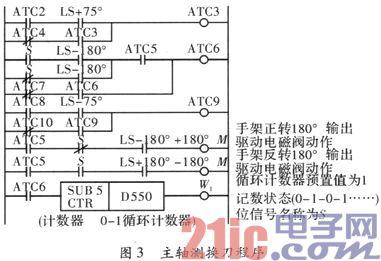
As shown in Figure 3, the paper improves on the Japanese FANUCOi system PLC program to meet the actual work needs. Cyclic technology is an important part of the program, and its working principle is similar to that of flip-flops in logic circuits. Its operation principle is as follows: The S signal in the PLC represents the counting state. When the S signal is “0†and “1â€, they represent the gripping and mounting claws, respectively. FIG. 3 represents the operating state change trend S of the loading knife. The change in the S state is related to the number of manipulator rotations, which change once per revolution. This system is powered down during operation, so no data loss occurs when there is a power outage or shutdown.
As can be seen from FIG. 3 , in the two tool change processes, when the M signal is transmitted to the mechanical circuit, the first time the machine outputs +180° and the second time outputs -180°. Therefore, the manipulator turns 180° for the first time, reverses 180° for the second time, and then enters action ATC6. When the manipulator is disassembled, it is necessary to set the corresponding 0 or 1 data according to the position of the manipulator, and the setting process is completed in the counter.
2. Detection and debugging methods for rotary axis position The machining center magazine produced through technology introduction can replace the absolute position encoder. The technical principle is shown in Figure 4. Two bit BCD codes DL1 to DL8, DH1 to DH4, and synchronization signal DB are obtained in the control system PLC input interface. For each tool position PG, the same BCD code as the tool position number will be given. According to the drive device of the starting tool chain, the PLC obtains the tool position corresponding to the output of the encoder and finally achieves accurate positioning.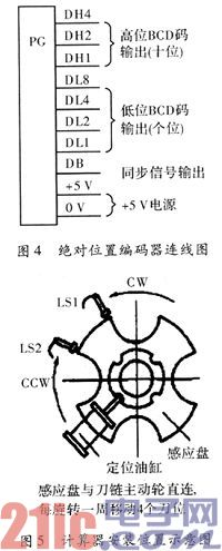
Considering the problems of cost and work efficiency, a set of economical and applicable location identification methods was designed. As shown in Fig. 5, a sensing plate is formed on the driving wheel of the knife chain, and the sensing plate is divided into 4 sensing intervals. For tool position rotation counting and position monitoring, two non-contact switches, LS1 and LS2, were additionally installed. Positioning control: When the PLC movement command is completed, the speed of the knife chain is slowed down based on the normal operating speed. When the LS1 and LS2 are turned on at the same time, the rotation of the machine is stopped, and then accurate positioning is performed. The program is shown in Figure 6.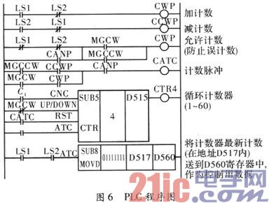
PLC includes plus/minus cycle counting device. The range of the program counting device is 1 to 60. The address of the power off and holding type cyclic counter is D515. The data format registered in D517 is the current counting value type. The count of tool magazines determined by the tool chain number sequence is triggered by the CCWP during forward rotation (MGCCW). The CMP triggers the magazine reverse count signal. When the tool bit rotates once, the counter counts up and down to prevent errors during the counting process. For example: The machine tool loses power or stops during normal operation. If you restart, the count will be wrong. To solve this problem, a special device CANP is designed in this paper. This device ensures that when the knife chain moves to LS1 and LS2, it does not sense the position to start until it stops before counting is allowed. For the smooth operation of the subsequent tool change program, the internal data of the D517 is saved to the D560 during the tool magazine operation. The machine does not need to worry about data loss caused by a sudden machine shutdown because the machine has a power failure protection function.
The debugging and use of the machine tool must be determined according to the actual work situation, and all problems cannot be solved in accordance with the unified template. The paper only analyzes the problems encountered before. In practice, the above methods are used to make the machine running stable and easy to debug. At the same time, it also improves work efficiency. Therefore, this method has better development and application prospects.
Keywords FANUC; PMC; CNC machine tool; debugging method In the numerical control machine tool industry, the numerical control system refers to the computer numerical control device, programmable logic controller, feed drive and spindle drive device and other related equipment. Sometimes it refers to the computer digital control device and the control device is called a numerical control device. The composition of the numerical control system and the role of various parts, as shown in Figure 1.

From the block diagram of the Position-Mate-A axis switching control in Figure 1, it can be seen that the single-axis CMC operating system is mainly applicable to tool magazines. This requires a continuous and more accurate positioning of the CMC system. The machining center consists of the following structures: Positioning controller, two servo motors, one servo unit. These devices are mainly used for the control of the magazine turntable. The machine tool has an advantage that the turntable and the magazine do not need to act at the same time, which avoids equipment wear due to friction and other reasons, so as to achieve the purpose of reducing costs.
The specific steps for the issuance and processing of program instructions are: (1) The CNC controller is responsible for issuing instructions to the PMC. (2) The PMC processes and issues control and movement instructions based on the calculations issued to the CNC. The role of the turntable operation instruction and the axis switching instruction is to change the operation mode of the controller. That is, the operation of the magazine is changed to the operation of the turntable. The specific flow is: (1) the servo is in the disconnected state; (2) the servo motor power line is switched; (3) the position controller is changed from the magazine mode to the turntable mode; (4) the servo is turned on; (5) the specified position is reached .
It is noteworthy that after the above steps are completed, the operation mode of the tool magazine is switched to, and the emergency stop signal needs to be switched to the controller emergency stop interface.
Many accidents usually occur during the operation of the machine tool. The operator must analyze it based on experience. When the tool magazine is violently shaken, the damage degree of the various components in the tool store will be deepened. This phenomenon occurs because the controller is in a reset state when the emergency stop is released. At this time, the operation mode of the axis is changed. However, actually, the instruction is not executed, so an abnormal axis switching action may occur. After analyzing and researching the above problems, it has been found that using common methods to solve this problem has not achieved good results. Through practical research, it has been found that using the following methods to solve this problem will have satisfactory results. That is, the output is in the off state during the conversion process, which will not cause severe vibration of the tool magazine. According to the above analysis, the PMC emergency stop circuit is improved, as shown in FIG. 2 .

The specific analysis is as follows: During the rotation of the turntable, press the emergency stop button. The ESP signal is switched on with the EMGB and then unlocked by itself. The signal will not change if the total power is not removed. Therefore, although the CNC has returned to the initial state, the EMGB signal is always "1", and the output signal for switching the turntable and magazine is always "0", which causes the two switching contactors to be powered off at the same time and positioning The controller and servo unit are in an alarm state. At this time, the CNC will send an alarm signal and information prompt. If you want to cancel the alarm, you must cut off the power and restart the machine. The above method can fundamentally eliminate the fault.
1. ATC loading and unloading knife status indicator debugging analysis A machining center uses a separate structure tool magazine robot and uses a hydraulic cylinder method to complete the tool changer. The robot rotates 180° clockwise on the spindle side to complete the tool change. The sensing block triggers LS+180° and thus proximity switches to get bit detection. In the next tool change process, the robotic arm reverses 180° to realize tool change, and the sensing block triggers LS+180° to approach the switch to obtain bit detection. From the analysis of the above-mentioned tool change procedure, it can be concluded that the manipulator needs a forward/reverse 75° motion to achieve the purpose of tool change. That is, in the course of each tool change, the frame only needs to rotate forward or reverse 180°.
It is difficult to determine whether the robot is transmitting or reversing 180°. Because the initial position of the robot's tool change is always at -75° and the position of the corresponding sensor block is not close to the switch, it is impossible to determine the specific position of the robot. If you can identify the position and state of the robot in the PLC, you can simply control the ±180° rotation direction.

As shown in Figure 3, the paper improves on the Japanese FANUCOi system PLC program to meet the actual work needs. Cyclic technology is an important part of the program, and its working principle is similar to that of flip-flops in logic circuits. Its operation principle is as follows: The S signal in the PLC represents the counting state. When the S signal is “0†and “1â€, they represent the gripping and mounting claws, respectively. FIG. 3 represents the operating state change trend S of the loading knife. The change in the S state is related to the number of manipulator rotations, which change once per revolution. This system is powered down during operation, so no data loss occurs when there is a power outage or shutdown.
As can be seen from FIG. 3 , in the two tool change processes, when the M signal is transmitted to the mechanical circuit, the first time the machine outputs +180° and the second time outputs -180°. Therefore, the manipulator turns 180° for the first time, reverses 180° for the second time, and then enters action ATC6. When the manipulator is disassembled, it is necessary to set the corresponding 0 or 1 data according to the position of the manipulator, and the setting process is completed in the counter.
2. Detection and debugging methods for rotary axis position The machining center magazine produced through technology introduction can replace the absolute position encoder. The technical principle is shown in Figure 4. Two bit BCD codes DL1 to DL8, DH1 to DH4, and synchronization signal DB are obtained in the control system PLC input interface. For each tool position PG, the same BCD code as the tool position number will be given. According to the drive device of the starting tool chain, the PLC obtains the tool position corresponding to the output of the encoder and finally achieves accurate positioning.

Considering the problems of cost and work efficiency, a set of economical and applicable location identification methods was designed. As shown in Fig. 5, a sensing plate is formed on the driving wheel of the knife chain, and the sensing plate is divided into 4 sensing intervals. For tool position rotation counting and position monitoring, two non-contact switches, LS1 and LS2, were additionally installed. Positioning control: When the PLC movement command is completed, the speed of the knife chain is slowed down based on the normal operating speed. When the LS1 and LS2 are turned on at the same time, the rotation of the machine is stopped, and then accurate positioning is performed. The program is shown in Figure 6.

PLC includes plus/minus cycle counting device. The range of the program counting device is 1 to 60. The address of the power off and holding type cyclic counter is D515. The data format registered in D517 is the current counting value type. The count of tool magazines determined by the tool chain number sequence is triggered by the CCWP during forward rotation (MGCCW). The CMP triggers the magazine reverse count signal. When the tool bit rotates once, the counter counts up and down to prevent errors during the counting process. For example: The machine tool loses power or stops during normal operation. If you restart, the count will be wrong. To solve this problem, a special device CANP is designed in this paper. This device ensures that when the knife chain moves to LS1 and LS2, it does not sense the position to start until it stops before counting is allowed. For the smooth operation of the subsequent tool change program, the internal data of the D517 is saved to the D560 during the tool magazine operation. The machine does not need to worry about data loss caused by a sudden machine shutdown because the machine has a power failure protection function.
The debugging and use of the machine tool must be determined according to the actual work situation, and all problems cannot be solved in accordance with the unified template. The paper only analyzes the problems encountered before. In practice, the above methods are used to make the machine running stable and easy to debug. At the same time, it also improves work efficiency. Therefore, this method has better development and application prospects.
Forged Block,Forged Steel Block,Stainless Steel Block,Metal Forged Block
Suzhou SNK Machinery Equipment Co.,LTD , https://www.snkforgedroll.com