Press Brake Structure and Components Explained
I. Introduction
The press brake is a machine used for sheet metal fabrication. There are a variety of press brakes, such as manual press brakes, mechanical press brake, CNC press brake, electro-hydraulic synchronous press brakes, and electric press brake. Currently, the most popular type of press brake is CNC press brake, also called an electrical hydraulic servo press brake.
The servo system and linear scale of the electrical hydraulic servo press brake can control the accuracy of the machine during operation. In the world of metal fabrication, the CNC control system can set all bending parameters to ensure the accuracy of the bending program.
The press brake structure and components are basically the same, merely differences in driving sources and individual sheet metal parts. Next, we will take the CNC press brake machine as an example and provide a detailed description of its key components and structures of a press brake.
II. Press Brake Structure and Components
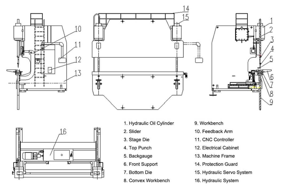
1. Mechanical System
Frame
The main structure that supports the entire machine, providing stability and support for the entire machine. It is usually a high strength fully welded C-shaped structure, and composed of vertical plates on both left and right, bed (workbench) and connecting structures.
The depth of frame is equivalent to throat depth, which offers much sheet metal bending space. There are also monitoring tools on the frame of the press brake, which can detect springback and keep it to a minimum.
Ram (Upper Beam)
The ram, or upper beam, moves the upper tooling (punch) vertically, forcing the metal sheet into the die to create bends. Driven either mechanically or hydraulically, the ram applies force to the workpiece, bending it against the die on the bed (lower beam). Precision in the ram's movement is vital for achieving accurate bends, and modern press brakes often incorporate advanced control systems to regulate this movement precisely.
Bed (Lower Beam)
The bed supports the die and the workpiece during the bending process. Made from high-strength steel, the bed must remain perfectly level to ensure accurate bends. It often features slots or grooves to accommodate various die configurations.
Side Housing
The side housing, or side frames, are vertical structures that connect the bed and ram, forming a rigid enclosure. These components maintain the alignment and stability of the common press brake, ensuring that the ram moves vertically without lateral deviation.
2. Hydraulic System

Hydraulic system is used to control the hydraulic cylinder’s pressure and flow rate. It mainly consists of motor, oil pump, oil filling valve, and oil cylinder, which are mounted on the press brake's frame, and there is an oil cylinder on each of the left and right vertical plates.
Power Source
The power source, typically an electric motor or engine, drives the hydraulic pump. This component provides the necessary mechanical energy to operate the pump, thereby powering the entire hydraulic system. Ensuring the power source is appropriately rated and maintained is essential for the system's reliability.
Hydraulic Pump
Hydraulic press brakes use hydraulic pump, which is the heart of the system, converting mechanical energy into hydraulic energy by moving hydraulic fluid through the system. Various types of pumps can be used, including:
- Gear pumps are simple and cost-effective, suitable for low-pressure applications. They are commonly used in smaller press brakes where high pressure is not required. An example of their application would be in automotive manufacturing for bending thinner metal sheets.
- Piston pumps are high-efficiency pumps capable of generating high pressure, ideal for demanding high-quality press brake operations. These pumps are often used in heavy-duty applications, such as the aerospace industry, where precise and powerful bending of thick metal sheets is required.
- Vane pumps are known for their quiet operation and efficiency, often used in medium-pressure applications. They are typically found in environments where noise reduction is important, such as in indoor manufacturing facilities.
Reservoir
The reservoir stores the hydraulic fluid and helps remove air and moisture from the system. It also compensates for fluid volume changes due to temperature variations and actuator movements. Proper maintenance of the reservoir, including regular fluid level checks and ensuring cleanliness, is crucial for the system's longevity.
Valves
Valves control the flow, direction, and pressure of the hydraulic fluid within the system. They play a critical role in ensuring precise and safe operation of the press brake. Key types of valves include:
- Directional control valves direct the flow of fluid to different parts of the system, enabling the movement of the hydraulic cylinders. For instance, these valves are crucial in switching the direction of the ram's movement during a bending operation.
- Pressure relief valves protect the system from excessive pressure by diverting fluid when the pressure exceeds a predetermined limit. This prevents potential damage to the hydraulic components and ensures safe operation.
- Flow control valves regulate the speed of the hydraulic fluid, allowing for precise control over the ram's movement. This is particularly important in applications requiring varying bending speeds, such as in custom metal fabrication.
Hydraulic Cylinders
Hydraulic cylinders are the primary actuators in a press brake's hydraulic system. These components convert hydraulic energy into mechanical force, driving the ram's vertical movement. The cylinders are typically filled with hydraulic fluid, and their movement is controlled by the pressure and flow of this fluid.
- Single-acting cylinders apply force in one direction only, usually for simple press brake operations. They are commonly used in applications of press brakes where the return movement can be achieved by gravity or an external force, such as in light-duty metal bending tasks.
- Double-acting cylinders are capable of applying force in both directions, offering more control and versatility. These cylinders are essential in advanced press brake systems used for complex bending operations, such as in the production of intricate metal components for machinery.
Hydraulic Circuit
The hydraulic circuit is a network of interconnected components through which the hydraulic fluid flows. It includes the pump, valves, cylinders, and plumbing (hoses, tubes, and fittings). The design of the circuit determines the system's efficiency and performance. Proper maintenance of the circuit, including regular inspections for leaks and ensuring all connections are secure, is vital for optimal operation.
Lubrication and Cooling
Hydraulic fluids not only transmit power but also lubricate the system's components and help dissipate heat. Selecting the right hydraulic fluid is critical, considering factors such as wear protection, thermal stability, and corrosion resistance. Regular fluid checks and changes are necessary to maintain system performance and prevent contamination.
Filter Element
Press brakes use the filter element to filter the liquid in the hydraulic system to keep the hydraulic system working properly.
3. Electrical System
Control System
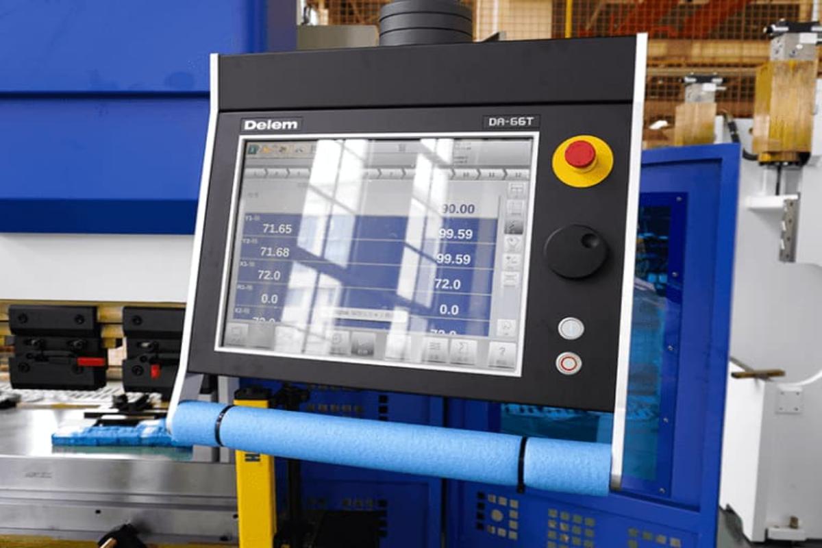
The control system is the brain of the press brake, managing the machine's operations through an interface that allows the operator to input commands. Modern press brakes come with CNC (Computer Numerical Control) systems, providing high precision and automation capabilities.
- CNC controllers, such as the Delem DA-66T or CybTouch 12 PS, offer advanced programming features, real-time monitoring, and diagnostics. These controllers enable operators to create complex bending sequences, store programs, and ensure consistent bending accuracy.
- Sensors and feedback devices play a critical role in maintaining the accuracy and safety of the press brake. These components include position sensors, pressure sensors, safety sensors.
Motors and Drives
Motors and drives are responsible for powering the movement of the ram, back gauge, and other various components. They convert electrical energy into mechanical motion, enabling precise control over the bending process.
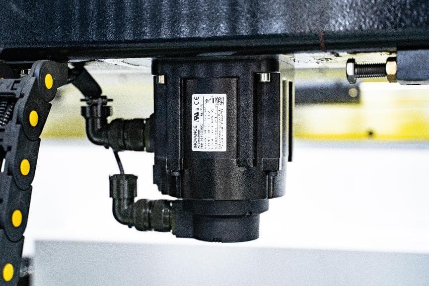
- Servo motors are commonly used in modern press brakes due to their high precision and reliability. These motors provide accurate control over position, speed, and torque, making them ideal for applications requiring fine adjustments. Compared to traditional motors, servo motors offer faster response times and higher efficiency, which enhances the overall performance of the press brake.
- Variable frequency drives (VFDs) control the speed of AC motors by varying the frequency and voltage of the power supplied. VFDs enhance the efficiency and performance of the press brake by allowing smooth acceleration and deceleration, reducing mechanical stress on components. They also provide energy savings and improved motor lifespan compared to conventional drives.
Electrical Panels and Wiring
The electrical panels house the various control components, including circuit breakers, relays, and contactors. Proper organization and labeling of these panels are essential for easy maintenance and troubleshooting.
Human-Machine Interface (HMI)
The Human-Machine Interface (HMI) is the user interface that allows operators to interact with the press brake. It typically includes a touchscreen display, buttons, and other input devices.
Safety Features
Safety is paramount in the design of the electrical system in press brake machines. Various safety features are integrated while using a press brake to protect both the operator and the machine.
- Emergency stop buttons are strategically placed around the press brake, allowing operators to quickly shut down the machine in case of an emergency. These buttons disconnect the power supply, halting all movements immediately.
- Light curtains and safety guards create a protective barrier around the working area. Light curtains use infrared beams to detect any obstructions. If the beams are interrupted, the press brake stops operating to prevent injury. Safety guards, on the other hand, physically block access to dangerous areas, ensuring that the operator remains at a safe distance during operation.
4. Tooling System
Punch and Die
- Types of punches: straight punch, gooseneck punch, offset punch
- Types of Dies: V-dies, radius dies, acute angle dies, gooseneck dies, bottoming dies
Tool Holding Systems
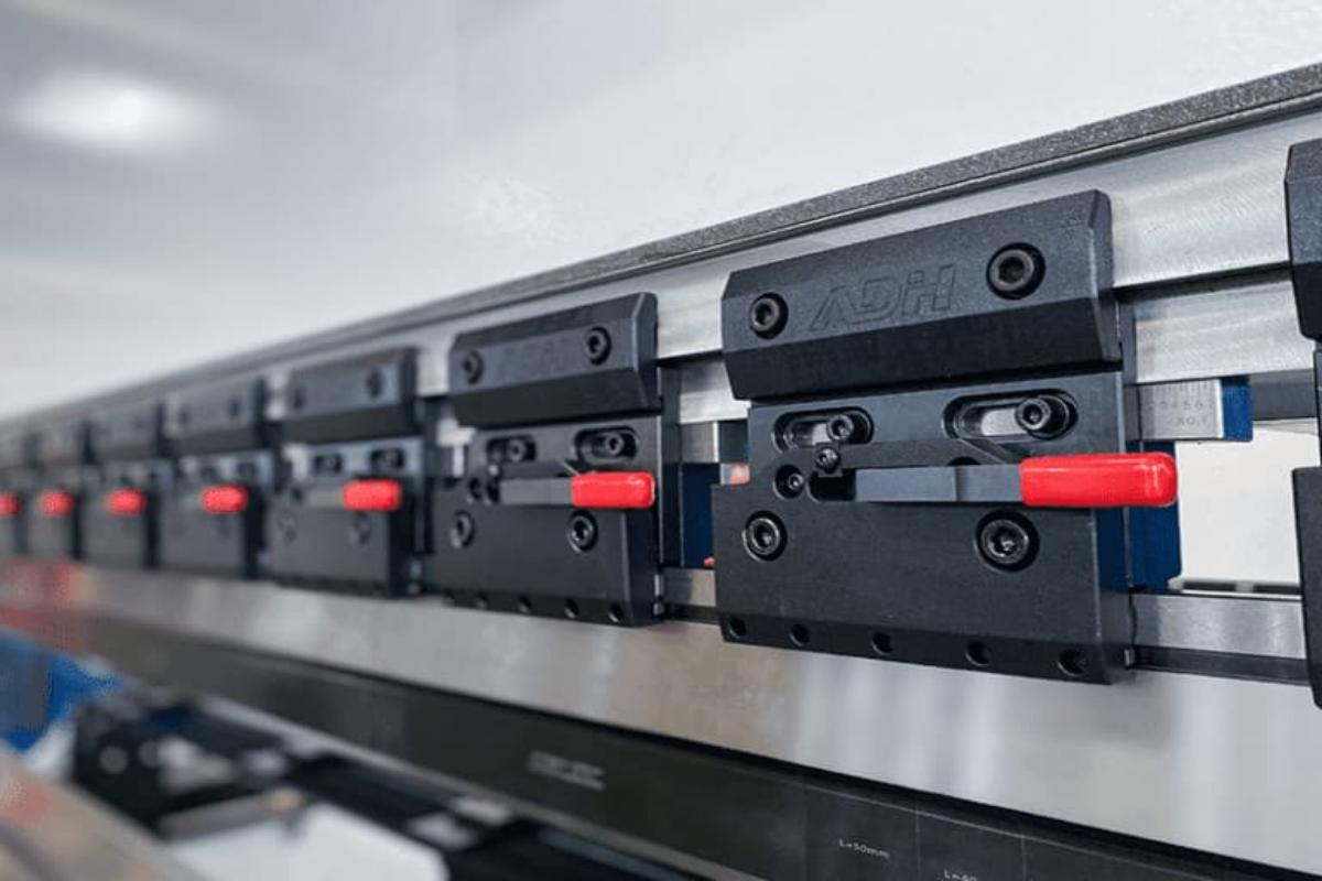
Press brake clamps are used to fix the tooling, and are divided into upper clamps and clamps on the workbench. During the clamping process, the upper clamps can automatically align the center. Clamps are also divided into ordinary clamps and fast tool clamps.
Fast clamp is a fast clamping and fixing device for top punch on the press brake. It locates on the ram of press brake and can be used to quick clamping and removal of top punch. It contains a fixture base and a front pressure plate device, which can adjust the die to ensure even force, prevent ram damage, and ensure the machining accuracy of the workpiece stably.
Tool Alignment Systems
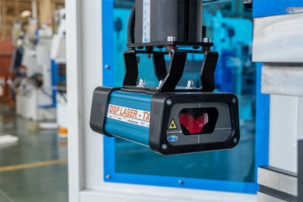
- Laser Alignment: Employs laser technology to ensure precise alignment of the punch and die, enhancing accuracy and reducing setup time. This system is beneficial in high-precision applications where exact alignment is critical.
- Mechanical Alignment: The press brake utilizes mechanical guides and stops to align the tools. While less advanced than laser systems, it is still effective for ensuring proper tool positioning and is commonly used in manual and semi-automatic press brakes.
5. Additional Components
Back Gauge
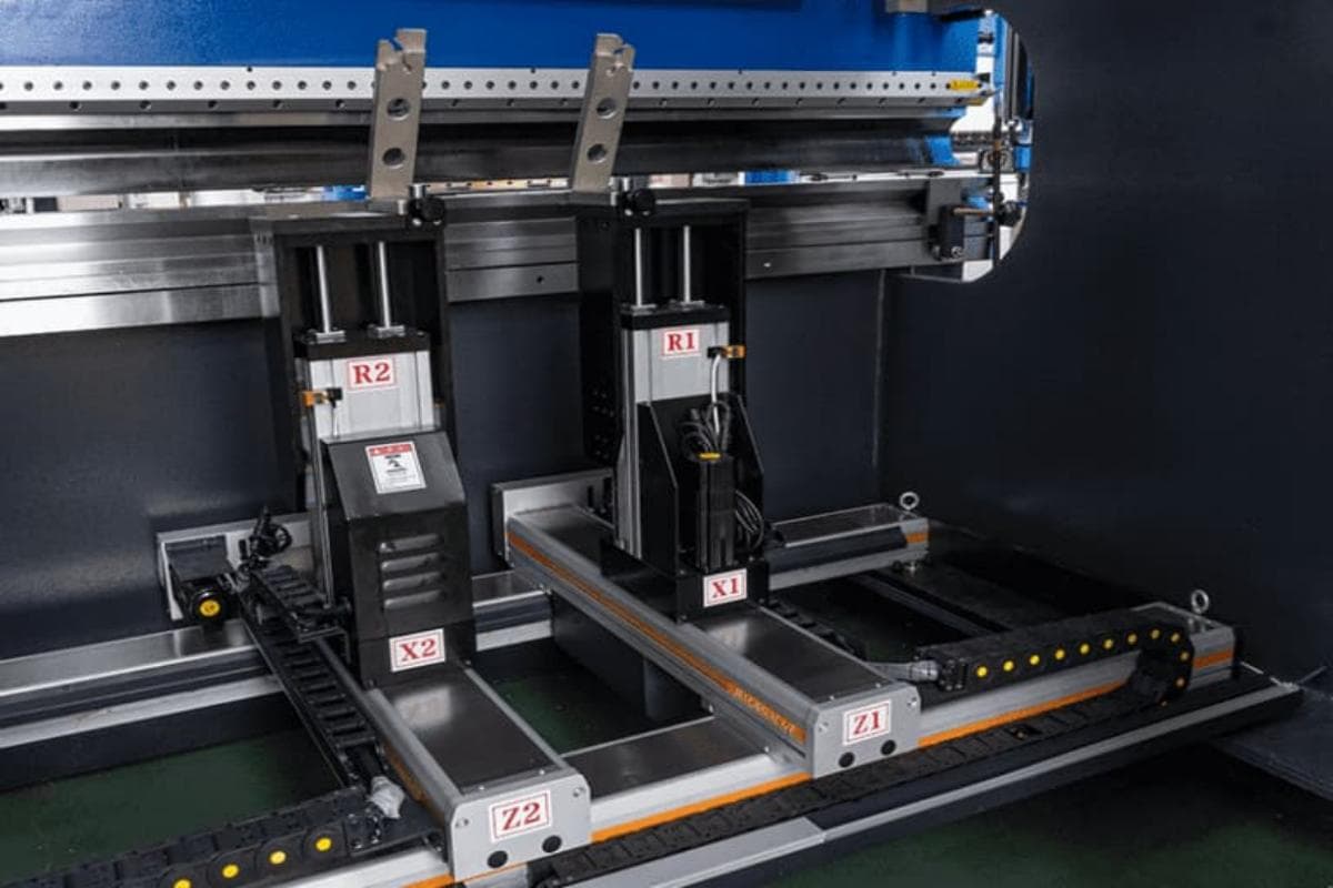
The back gauge is a paramount part of the press brake, which is used to control and adjust the position and length of the piecework during the bending process. It locates on the rear of the press brake, and precisely position the workpiece before bending.
Besides, it is driven by different motors and moves on different axes. The ball screw and timing belt ensure the synchronous movement of the back gauge. The back gauge is controlled by the CNC controller and can move on 6 different axes.
The R-axis indicates upward and downward movement. The X-axis represents forward and backward movement. The Z-axis indicates left and right movement. During bending, the workpiece is placed on the die of the workbench. Push the workpiece to fit with the stop finger. The back gauge has many stop fingers connected with the workpiece.
The main function of the back gauge is to limit the movement of the piecework during bending and to ensure that the piecework is bent in the correct position. It can be controlled and adjusted by motor, servo motor or cylinder. The operator can set the position and length of the back gauge through the control system of the press brake to meet the bending requirements of different piecework.
(1) Stop finger
Stop finger is a component that displays the size of the processed piece when the front and back gauge change the displacement. The stop finger can move smoothly on the linear guide rail, and can also be adjusted up and down, which is convenient, efficient and easy to control.
The press brake generally has multiple stop fingers, according to the actual demand configuration of the number, it is a point contact, and can avoid the problem of insufficient straightness of the plate, realizing the bending of different lengths of sheet metal parts.
(2) Back gauge bar
Back gauge bar is a rod-shaped assembly used with the stop finger to move and adjust the position of the stop finger by electric or hydraulic drive. The position adjustment of the back gauge bar can be precisely controlled by the control system.
(3) Back gauge sensor
Back gauge sensor is applied to test the position and length of the piecework. It can inform the control system position through feedback signal, thus achieving more precise location.
(4)Â Back gauge controller
Back gauge controller is an electrical device, used to control the back gauge. It receives the signal from back gauge sensor and realizes the piecework location adjustment through controlling the back gauge bar.
(5)Â Back gauge guide rails
Back gauge guide rails are a guide rail system installed on the bed, which are used to support and guide the movement of the back gauge bar. And it ensures the bar keeps steady and precise while moving along the bed.
Crowning
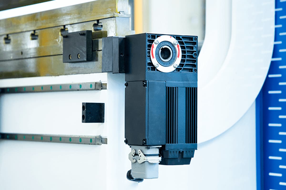
A crowning system compensates for deflections in the press brake's bed and ram during bending, ensuring uniform angle and bend quality across the entire length of the workpiece. It features numerous functions, such as angle crowning, length crowning, gap error crowning, etc.
- Hydraulic Crowning: Uses hydraulic pressure to adjust the bed automatically, providing more accurate compensation and ease of use. In modern press brakes, hydraulic crowning systems are common and ensure consistent results. Data indicates that hydraulic crowning can improve bend accuracy by up to 30%, making it highly valuable for more demanding applications.
- CNC Crowning: CNC press brake is controlled by CNC system, this automatically adjusts during bending operations for optimal compensation, ensuring high precision and repeatability. In industries requiring high precision, CNC crowning systems are indispensable.
Front Support
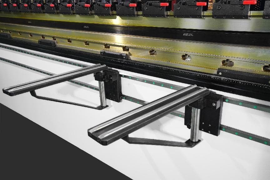
Front support is used to support metal sheet being bent and can be adjusted up and down. It is equipped with guide rails and can move automatically. It is more safer and stable compared with manual support, thus achieving better bending results.
Crane Arm
The crane arm is used to hang or support the small control box, which can be turned around in all directions. It boosts a good load-bearing press brake's capacity and a strong and solid structure. It is mostly made of high-quality aluminum alloy with open molding.
Foot Pedal
The foot pedal is one of the four main components (operator, equipment, system, foot pedal) in the operation of the press brake. It integrates emergency stop, cycle, and single-step remote control functions.
The foot pedal allows for the free control of the back gauge left and right movement, as well as the machine's start and stop functions, and integrates control of the machine tool. What’s more, it can be added with a WIFI module for networking, enabling seamless monitoring and management across the entire area, and offering simplified management capabilities.
Linear Scale
Linear scale serves for measuring and controlling the location and angle during bending process. It can be installed on the top punch or bottom die of the press brake. It is used to measure the location of top punch or bottom die accurately, and control the motion of press brake timely.
Linear scale boosts for its high precision and high definition, which can meet your expected requirements, improving the precision and stability in bending process.
III. FAQs
1. What is a press brake, and what is it used for?
A press brake is a machine tool used to bend sheet and plate material, typically metals, by clamping the workpiece between a punch and die. It is commonly employed in sheet metal fabrication industries to produce parts with specific angles and shapes, supporting applications such as forming channels, brackets, and structural components.
Press brakes are essential in industries like automotive, aerospace, and general manufacturing due to their precision, versatility, and capacity to handle a variety of metal thicknesses.
2. What are the primary components of a press brake?
Key components of a press brake include the frame, ram, bed, backgauge, punch, and die. The frame provides structural stability, while the ram moves vertically to press the punch onto the workpiece positioned over the die.
The backgauge assists in positioning the metal accurately for repeatable bending, and the control unit—manual, NC, or CNC—governs the operation and precision of the machine. Understanding these components and their roles is essential for effective press brake use and maintenance.
3. What are the differences between hydraulic, mechanical, and electric press brakes?
Common press brakes can be divided into hydraulic, mechanical, and electric press brakes. They differ in their operation and applications. Hydraulic press brakes are favored for their powerful force and flexibility, accommodating varying stroke lengths, which makes them suitable for thick and heavy materials.
Mechanical press brakes are precise and fast, driven by a flywheel but are generally limited to lighter tasks. Electric press brakes, known for energy efficiency and speed, offer high-precision control and are suitable for lighter or moderate applications where energy conservation and noise reduction are essential.
Each type has unique advantages, so understanding these differences helps in selecting the appropriate press brake for specific fabrication needs.

Door And Window Sealing Strip Series
Door And Window Sealing Strip Series,Door Rubber Seal Strip,Door Window Frame Seal Strip,Window Sealing Strip
HEBEI JIEXING RUBBER SEALS CO.,LTD , https://www.jiexingrubber.com